Fm 200 System Wiring Diagram
For speed in suppressing fires, reducing damages, saving on floor space and allowing visibility, Fike is the clear choice.
Fm 200 system wiring diagram. As such, it must be performed in accordance with NFPa 96 (Standard for the Installation of Equipment for the Removal of Smoke and grease-Laden. The FM-0 is designed to be installed directly below the dispensing !. Kidde fire systems since 1917 kidde fire systems has been a global leader in fire protection protecting people property and processes from fire hazards our fire protection solutions include conventional intelligent detection and control.
If two detector actuate (cross – zoning – This is done to prevent false alarm) then and only then is the timer in the panel is actuated. The panel shall accept input from the following types of equipment used to make up the system:. Re-acceptance testing is also required after any addition or deletion of system components, and after any modification, repair or adjustment to system hardware or wiring.
We will share this website for you articles and images of wiring diagrams, engine schemes, engine problems, engine diagrams, transmission diagrams. When properly designed, the FM-0 system will suppress surface burning fire in Class A, B, and C hazards. Description Units Measurement Molecular Weight N/A 170.03 Boiling Point at 760 mm Hg °C -16.4 ˘.
Wiring Diagram for Dual Pressure Switch (-24) Arabic Language Warnings. Find Your Product or System Name:. FM0 Plus Installation Manual Version :.
3.2.9 FM-0 Warning Nameplate 10 4 SYSTEM DESIGN AND LIMITATIONS 11 4.1 General 11 4.2 Design Procedure 11 4.3 Hazard Enclosure Size Limitations/Nozzle Placement 12 4.4 General Specifications 14 4.4.1 Discharge Time 14 4.4.2 Storage and Operating Temperature Range 14. Find the marine product manual you need at ManualsOnline. P/N 06 r297 Rev.
The system shall provide a FM-0 minimum design concentration of 7.2% by volume for Class A hazards and 9.0% by volume for Class B hazards, in all areas and/or protected spaces, at the minimum anticipated temperature within the protected area. FM-0 Extinguishing System 51 Codes and Standards 53 NFPA 53 UL 55 FM 55 iv Siemens Building Technologies, Inc. When designing a system that will be entered from a highway or main thoroughfare, make sure the system is placed far enough from the road to prevent traffic congestion.
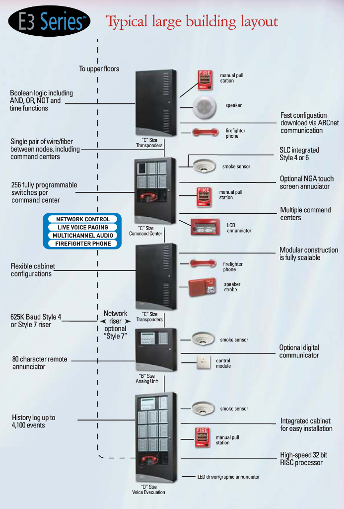
19 December 02 Page 3 of 15 Introduction System Overview The VDO Fleet Manager 0 Plus (FM0 Plus) is an on-board-computer for use in vehicles and working machines. 3-3.21.1 SPECIAL PROCEDURES FOR NETWORKED SYSTEMS The following paragraphs describe how a networked ARIES system must be configured, initialized, tested, and commissioned. SIEMENS FIRE DETECTION AND ALARM SYSTEM BASICS This course is intended to explain the configuration of automatic fire detection and alarm systems from a very basic view point.
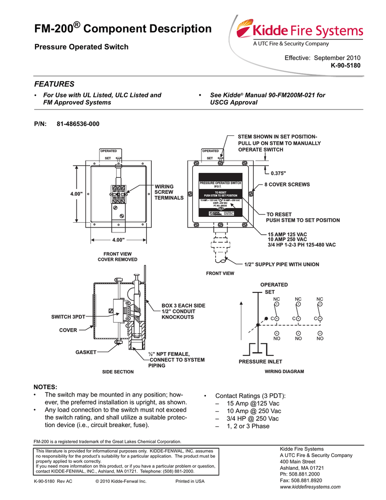
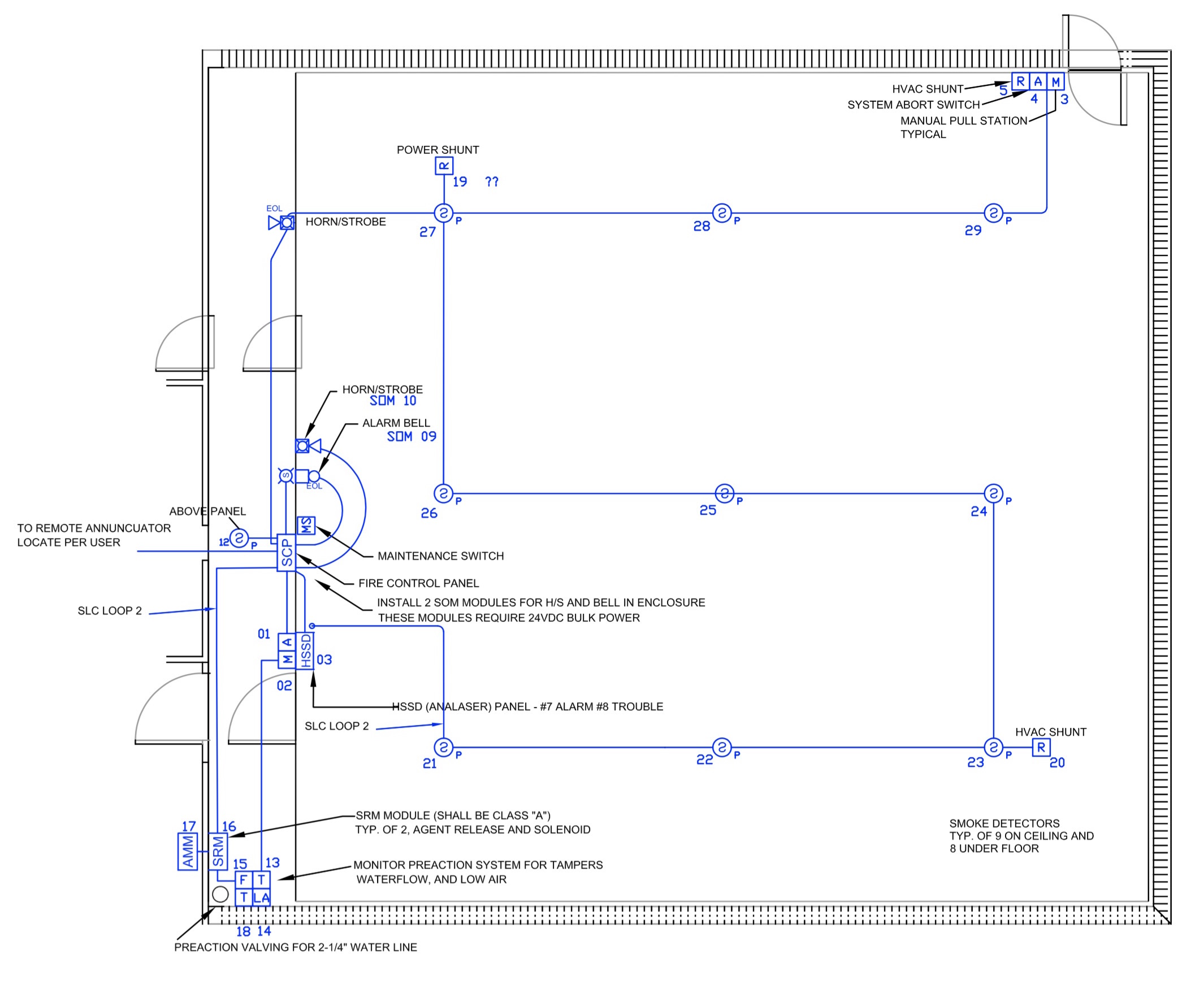
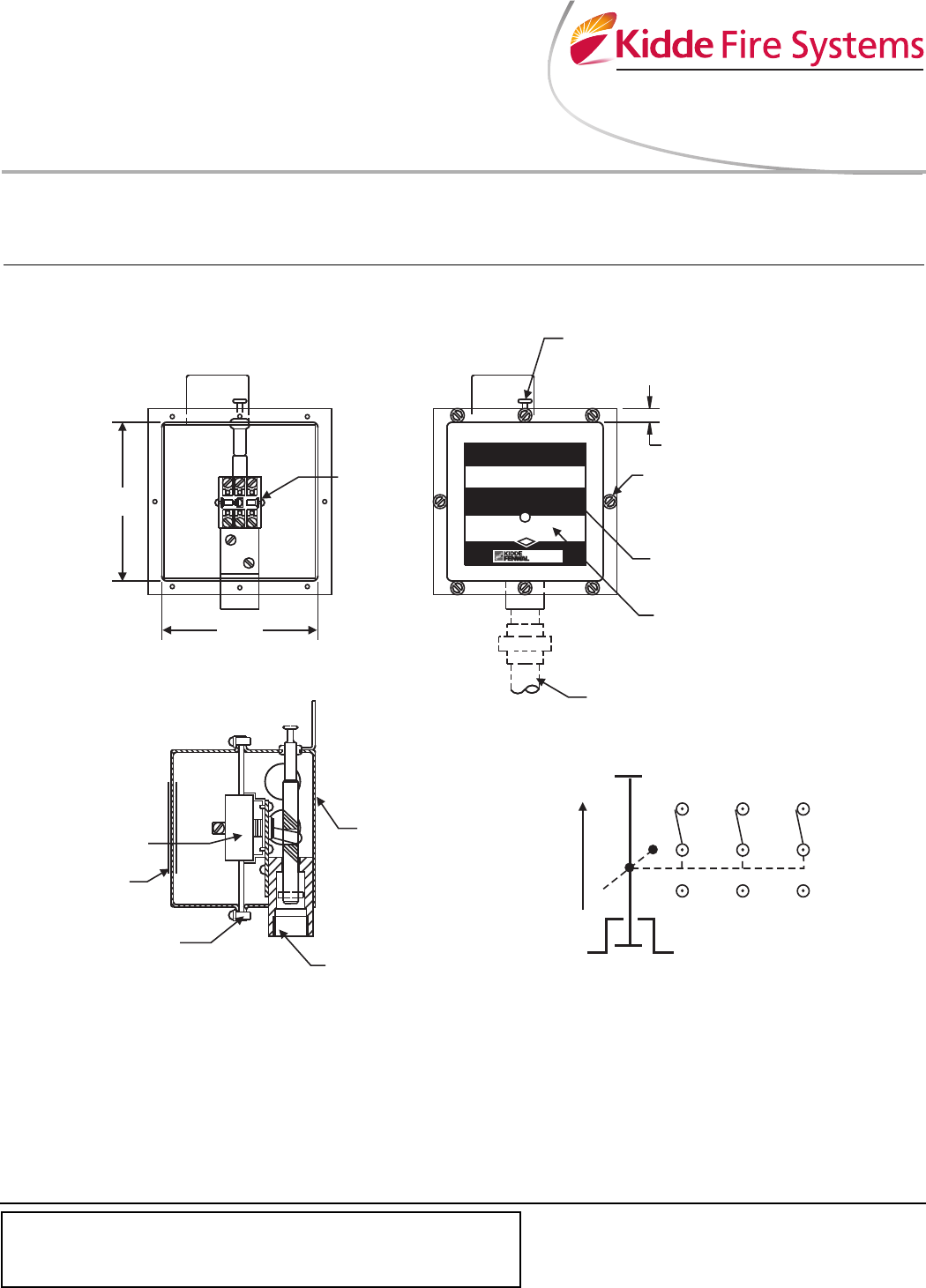
METRON “SYSTEM ARMED” THE KEY CAN BE REMOVED TO. A) The system shall be a Total Flood fm-0 Suppression System supplied by:. These switches, in turn, energize the alarm system's strobe lights, horns, and bell.
FM-0 Suppression Systems Historically, the most widely used Halon 1301 replacement, FM-0™ provides waterless fire suppression without leaving behind residue or particulate, and has been installed in over one hundred thousand applications in more than 70 nations. The system shall provide the FM-0 fire extinguishant minimum design concentration of 6.7% (UL) or 7.17% (FM) by volume for Class A hazards and a minimum of 8.97% by volume for Class B hazards, in all areas and/or protected spaces, at the minimum anticipated. Tie-in of FM-0 panel to house fire alarm and/or security system.
To find a diagram for a specific product or system, please use the drop-down menus below. When the FM-0 system is actuated, pressurized CO 2 from the system's actuating circuit closes the alarm system's pressure. $ ˝ ˙ !.
Revision F Document DOC102 Issued:. Page 2 away from heat. WIRING DIAGRAMS Figure 1 and Figure 2 show wiring diagrams for the Key Maintenance Bypass Switch.
And maintain the PYRO-CHEM system. Specify the Product or System. Automatic Fire Extinguishers High Pressure Co2 Low Pressure Co2 FM-0 Fire Suppression Novec-1230 Fire Suppression Fire Detection Systems Flame and Gas Detection Solutions Foam.
System Re-acceptance Test after Re-Programming:. Dozens of Honeywell Addressable Devices With Fire System Wire Diagram Html wiring diagram examples let you be instantly productive. Novec 1230 DLP Systems, Warnings Only (Arabic) Novec 1230 ILP Systems, Warnings Only (Arabic) FM-0 DLP Systems, Warnings Only (Arabic) Dry Chemical ILP Systems, Warnings Only (Arabic) French Language Warnings.
FM-0® OPERATION, DESIGN, & SERVICE MANUAL. 80% of FM-0 fire fighting effectiveness is achieved through heat absorption and % through direct chemical means (action of the fluorine radical on the chain reaction of a flame). ˙ ˙ ˆ ˛>.
The system shall be a Total Flood FM-0 Suppression System supplied by PYRO-CHEM. The gate must be installed in a location that provides adequate clearance between it and adjacent structures when opening and closing to reduce the risk of entrapment. Sounding, the occupants of the engine room and AMS 1 have 60 seconds to evacuate the space prior.
Page 1 ® fm0 model ft fire extinguishers installation instructions owner’s manual this manual is an integral part of the system and as such, the extinguisher must be installed and maintained accordingly. Exhaustive Wiring Symbol Library You get hundreds of ready-made wiring symbols. The system shall provide the FM-0 fire extinguishant minimum design concentration of 6.7% (UL) or 7.17% (FM) by volume for Class A hazards and a minimum of 8.97% by volume for Class B hazards, in all areas and/or protected spaces, at the minimum anticipated temperature within the.
24 vdc indicator lamp 24 vdc power source (+) (–) key-operated lock-out switch control unit release circuit terminals or addressable release control module* polarity is shown in alarm. Once the alarm begins. $ ˝ ˚ ˝˝ ˛ "!.
Fire suppression system disconnect 4 11/16 in. 1 VAC power to the FM-0 panel, graphic annunciators and maintenance panel. Wiring Diagram, Release Circuit with Key Removed Figure 2.
Wiring Diagram, Detection Circuit with Key Removed GREEN LED EOL DEVICE (P/N --0) N.O. Search the Lutron archive of wiring diagrams. Prior to removing the actuator from the Fike system bottle, the device must be properly shunted according to the following procedure to prevent accidental discharge:.
- wiring diagrams and cable specification - operating instructions - fm0 flow calculations Gielle analyzes the fire hazard potential and recommends the best way to protect your people and equipment for the least expense. Keep away from child. (117 mm) 2 5/8 in.
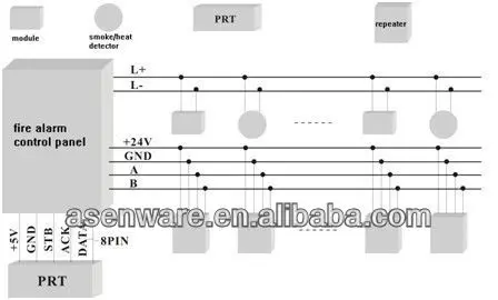
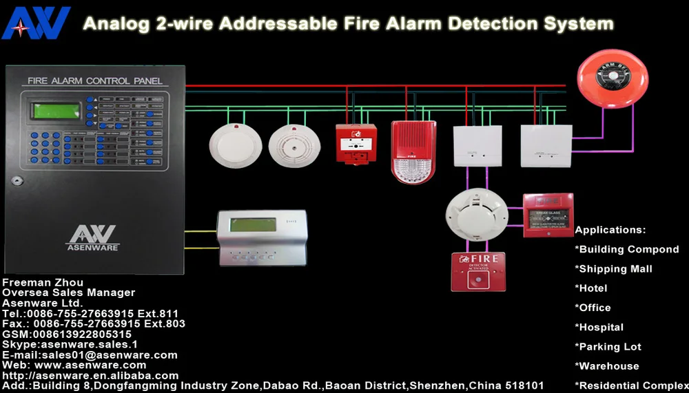
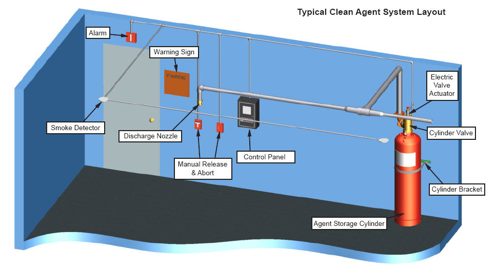
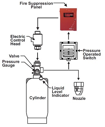
The Detectors detect smoke and give an alarm. They need periodic care. #˝ ˝ ˝˝ ˛ ˙ !.
The FM-0 fire suppression system is one of the most well-recognized and respected clean agent fire suppression systems in the world today. 1.1 Listings and Approvals 2 Extinguishing Agent 2. FM 0 is a halocarbon agent accepted as an alternative to halon for total flooding fire suppression systems.
Confires provides complete FM-0 system services, including sales, installation, inspection, recharge, testing, and more. Wire the blue and red wires together, and secure with a wire nut or electrical tape. Nov 13, 14 - inControl Systems has been active for over 30 years, delivering full fire solutions around the world in every industry.
Marine manuals and free pdf instructions. Kidde fire systems krs 100 user s manual manualzz com krs 50 control box fm 0a manualzz com. 3-3.21.1.1 Network-Interface-Card (NIC) Installation and Wiring Follow the instructions in Paragraph 2-17.1 to install each NIC.
Since 1917, Kidde Fire Systems has been a global leader in fire protection, protecting people, property, and processes from fire hazards. We also have an FM-0 system installation guide!We can provide the inspection and maintenance schedule to keep your system in compliance, as well as keep accurate. Still installed in the fire protection system).
Fire Suppression System Wiring Diagram– wiring diagram is a simplified up to standard pictorial representation of an electrical circuit.It shows the components of the circuit as simplified shapes, and the capacity and signal connections in the company of the devices. Guys learn how to make FM 0 - Detector 4098 wiring #FM0 #FM0Detectorwiring #TheEngineersAdvice Hello Guys, Please watch All FM0 videos Subscribe My C. 1 GENERAL INFORMATION 1.
The system shall be a Total Flood FM-0 Fire Suppression System supplied by Tyco. The best feature of this system is that it can reach extinguishing levels in 10 seconds or less, which allows the FM-0 to halt combustible, electrical and flammable liquid fires. Included in the microswitch kit is the microswitch, pigtail assembly, mounting screws, and wiring diagram label.
To ensure proper system operation, this system must be retested in accordance with NFPA 72 Chapter 10 after any programming change. It does not cover fire extinguishing systems that use carbon dioxide or water as the primary extinguishing media, which are addressed by other NFPA documents. Interlock conduit and wiring to ventilation equipment, dampers, and shunt-trip breakers 3.
FM-0 System Services in New Jersey & Delaware FM-0 Sales | Installation | Inspection | Testing & Service. CO2 MYTH • “Everyone is buying FM-0® and CO2 is going away” Feb 01, Anonymous Kidde Employee • “Halon will replace CO2” Kidde Employee, circa 1970 (attributed) • “Hey, I have something better than steam!” Walter Kidde 1917 (paraphrased) 2. Smoke detectors, thermal detectors, and m anual pull stations.
1.3 Safety Considerations 2. Hello Guys learn FM 0 Fire suppression Release System - Wiring and operation. 1 Part Number , Revision F, 09/11/14 CG2 & M Series Clean Agent HFC-227ea CG2XXXX227-BXXXX Sizes:.
February 1, 09 Revised:. (67 mm) typical wiring diagram 24 vdc actuator n.c. B) The system shall provide an fm-0 minimum design concentration of 7.0 %, by volume, in all areas and/or protected spaces, at the minimum anticipated temperature within the protected area.
Fire suppression systems are mechanical devices. (119 mm) 3 in. Fire Suppression System Wiring Diagram - Welcome, thank you for visiting this simple website, we are trying to improve this website, the website is in the development stage, support from you in any form really helps us, we really appreciate that.
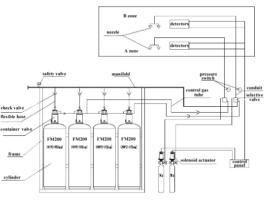
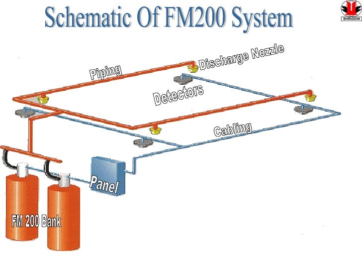
During fire, if a wire breaks, Class A Wiring provides an alternate route for signals to pass between field devices and the fire alarm panel. This standard contains minimum requirements for total flooding and local application clean agent fire extinguishing systems. After receiving the fire signal, FM 0 is discharged totally from the cylinders within 10 seconds to fill up the space uniformly at the design concentration to extinguish the fire.
The system consists of the following2) Detection System:. #FM0 #FireSuppressionReleaseSystem #TheEngineersAdvice Subscribe My Channel. We look forwarding to using our experience to tailor your solution.
Jul 2, - Explore Saad Hamed's board "Fire" on Pinterest. Position the FM-0 on the wall below the dispenser Pumpstand with the water inlet and flush discharge fittings on the desired end. The Quick Connect Microswitch used with the XV Control System is a single pole, double-throw switch (Figure 1).
5 / July, 17. ˆ ˘˙˙ ˆ ˝˝ ˛ ˝ = ˙ $ ˝ :. 2 SYSTEM DESCRIPTION AND COMPONENTS 5.
Electrical installation simply requires connecting a plug connector to the underside of the Pumpstand. Read and comply with these instructions, warnings and limitations before installing. Kidde fire suppression system wiring diagram another graphic:.
Strip the ends of all 4 actuator wires. GENERAL The FIREFLEX® 1230 integrated system consists of a clean agent fire extinguishing system, factory-assembled in a single cabinet. All the components necessary for the extinguishing system are integrated.
See more ideas about Fire, Fire sprinkler system, Fire sprinkler. ˝ ˛ ˙ ˝ ˝ ˙ # ˙ "!. FIKE Corporation 704 South 10th Street Blue Springs, MO.
Maintenance is a vital step in the performance of your fire suppression system. Complete suppression using FM-0 has the following. (76 mm) 4 5/8 in.
Located in over 80 countries worldwide, our highly skilled Authorized Distributor network designs. Ariadni / Toggler dimmer;. Simply select a Honeywell Addressable Devices With Fire System Wire Diagram Html wiring diagram template that is most similar to your wiring project and customize it to suit your needs.
Our Clean Agent Fire Protection System, which includes the use of HFC-227ea and FM-0™, leaves no residue and doesn’t require costly clean-up, unlike sprinklers and other fire protection systems.And it discharges in 10 seconds or less, extinguishing a fire quickly and. The FM-0 control panel shall be a Kidde, Aegis Control Panel, and shall perform the functions necessary to operate the detection, control and release of the FM-0 Suppression System. Our fire protection solutions include conventional & intelligent detection and control systems which complement a complete line of fire suppression systems.
2.1 Cylinder Assembly 6. The system and components shall be a Kidde Fire Suppression System as. Fm 0 schematic 1.
Class A wiring in a fire alarm system uses a primary signal path to all the devices, and if the signal path is interrupted, Class A wiring uses the Class A Return wires as an alternate pathway the signals.

Diagram Volvo Fm Truck Wiring Diagram Service Manual Download September 10 Full Version Hd Quality September 10 Oceandiagrams Photosportroma It

Fm0 Fire Suppression System Gas Detector System For Fire Alarm System Price China Extinguishant Control System Fire Suppression Systems Made In China Com
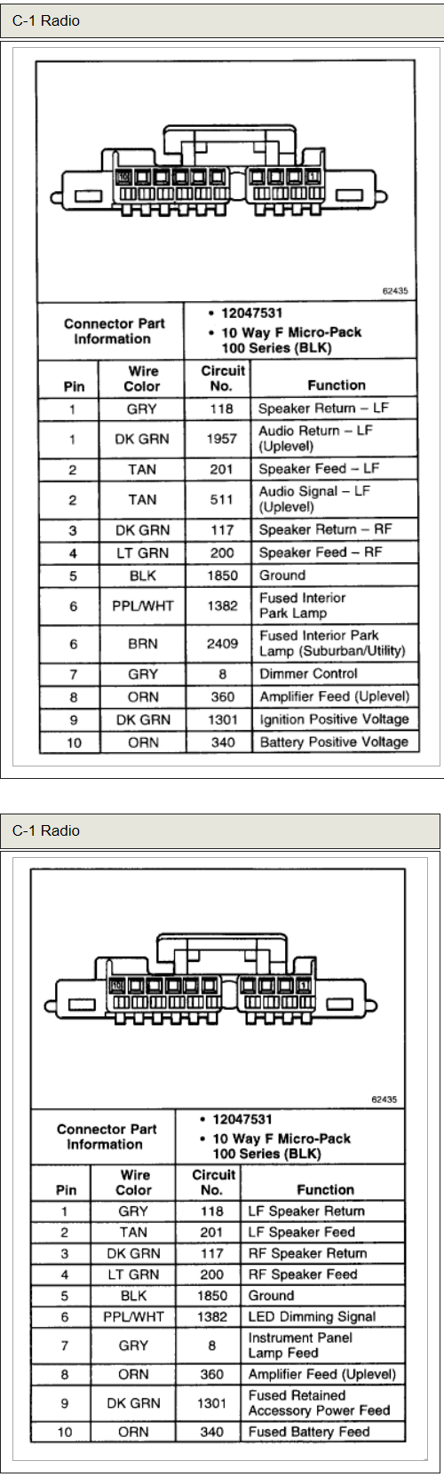
Chevrolet Car Radio Stereo Audio Wiring Diagram Autoradio Connector Wire Installation Schematic Schema Esquema De Conexiones Anschlusskammern Konektor
Fm 200 System Wiring Diagram のギャラリー
Kidde Fire Systems Fm 0 User S Manual Manualzz
Http Www Sffeco Com Pdf System Fike Pdf

Safety Equipments Fire Extinguishers Fire Fighting Equipments Fire Hydrant Water Sprinkler Systems Fire Alarm Smoke Detector System Ndustrial Safety Wear Fire Fighting Equipments Fire Hydrant Systems Fire Alarm Systems Fire
Www Vikinggroupinc Com Sites Default Files Documents F 19 1 R00 V00 Installation Maintenance Manual Vsh0 En Novds Pdf
Http Ravelfire Com Wp Content Uploads 15 06 Re316 Installation Manual Pdf

Diagram 03 Chevy Tahoe Radio Wiring Diagram Full Version Hd Quality Wiring Diagram Mediagramltd Villananimocenigo It
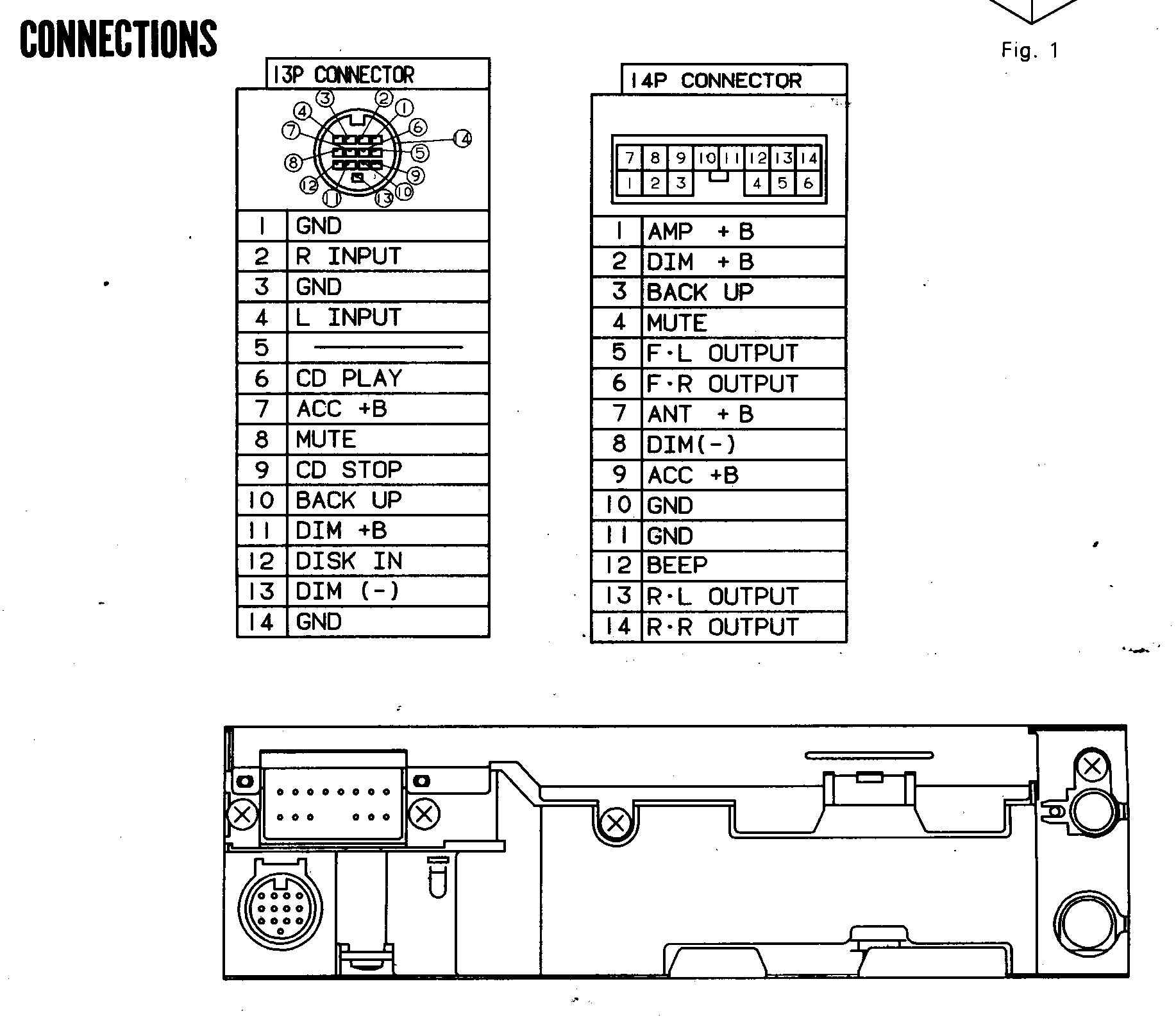
Diagram Pioneer Cd Player Wiring Diagram Full Version Hd Quality Wiring Diagram Eardiagrams Eracleaturismo It

Diagram Camaro Wiring Diagram 14 Radio Full Version Hd Quality 14 Radio Tabletodiagram Comprensorioaltavalsugana It

The Speaker Wiring Diagram And Connection Guide The Basics You Need To Know

Wiring Diagrams Bay City Metering Nyc
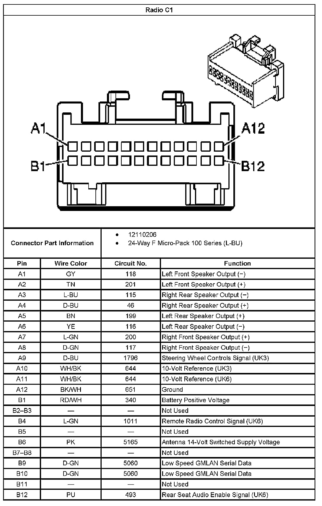
Diagram Car Stereo Wiring Diagram For Millions Full Version Hd Quality For Millions Logicdiagram Radiostudiouno It

Diagram Class B Fire Alarm Wiring Diagram Full Version Hd Quality Wiring Diagram Cs130wiringdiagram Triestelive It
Widar Fire Protection
Diagram Np Sensor Tester Wiring Diagram Full Version Hd Quality Wiring Diagram Classrelationdiagram Veneziaartmagazine It

Diagram 1991 Volvo 740 Wiring Diagram Full Version Hd Quality Wiring Diagram Randbcustomwiring Amichediviaggio It
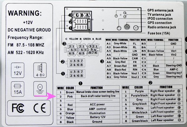
Rover Car Radio Stereo Audio Wiring Diagram Autoradio Connector Wire Installation Schematic Schema Esquema De Conexiones Stecker Konektor Connecteur Cable Shema

Diagram 1995 Chevy Truck Stereo Wiring Diagram Full Version Hd Quality Wiring Diagram Randbcustomwiring Amichediviaggio It
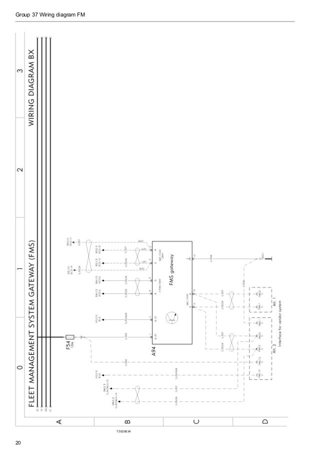
Wiring Diagram Fm Euro5

Diagram 05 Chevy Silverado Radio Wiring Diagram Full Version Hd Quality Wiring Diagram Antiqueradiodiagrams Shia Labeouf Fr
Simplex Fire Com En Us Documentsandmedia S4007 0003 Pdf
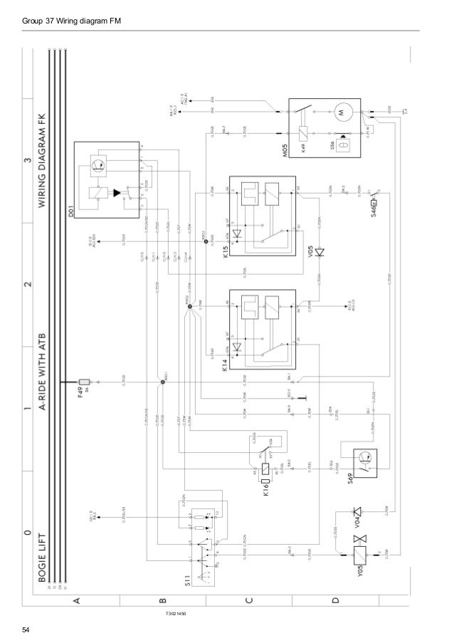
Wiring Diagram Fm Euro5
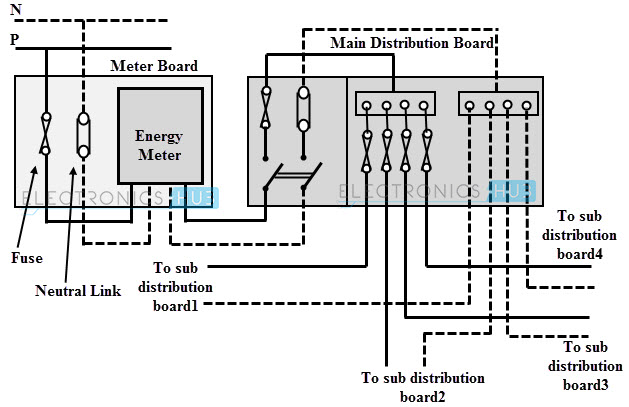
Electrical Wiring Systems And Methods Of Electrical Wiring
Q Tbn 3aand9gcrqnudmd3vyrz8yfiozququo5ww2pwcu6 Ilvatpzuvtvrn2k0 Usqp Cau
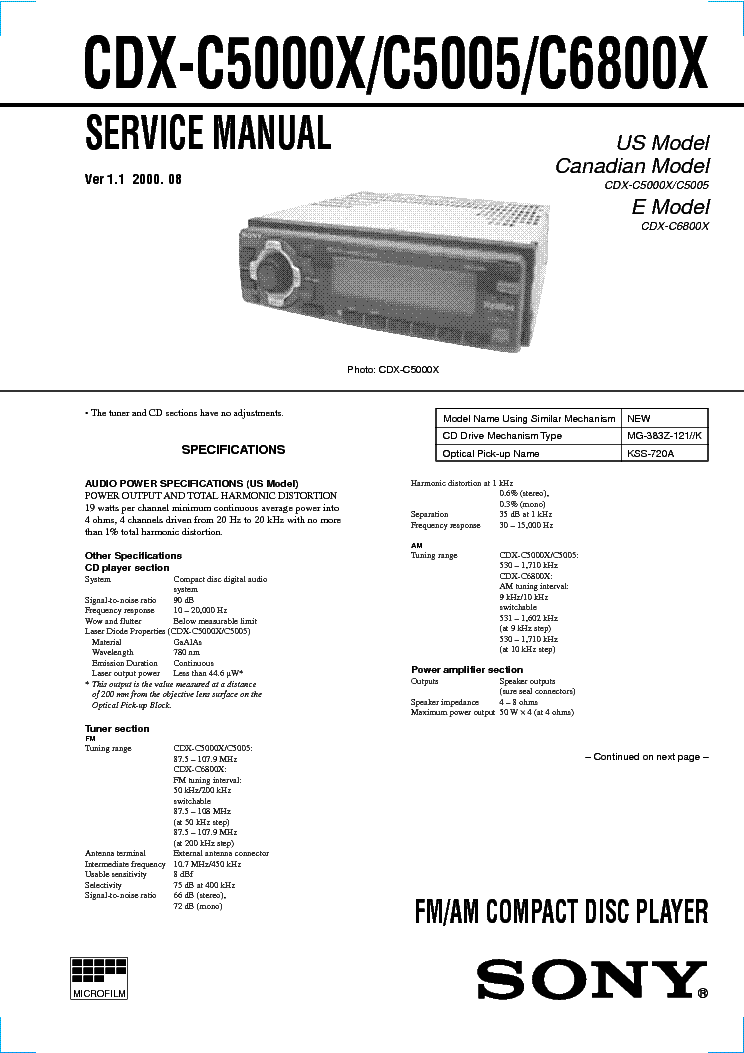
Diagram Sony Wiring Diagram Cdx C5000x Full Version Hd Quality Cdx C5000x Aftdischematic8030 Caferestaurant Letilleul Fr

Saab 93 Audio Wiring Diagram Full Hd Version Wiring Diagram Mahi Diagram Mille Annonces Fr

Diagram 04 Gmc Sierra Radio Wiring Diagram Full Version Hd Quality Wiring Diagram Doordiagram Sergesimon Fr
2 Wiring Bus 1 Loop Addressable Fire Alarm Sprinkler Fm 0 System Buy Fire Alarm System Gsm Fire Alarm Systems Gent Fire Alarm System Product On Alibaba Com
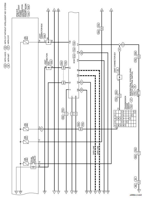
Nissan Sentra Service Manual Wiring Diagram Engine Control System Engine
Http Www Minimaxfp Com Sites Default Files Rot 053 Hfc Installation Manual Us V05 Pdf

Diagram Wiring Diagram 00 Land Rover Full Version Hd Quality Land Rover Mediagramltd Villananimocenigo It

Fm 0 Fire Suppression Systems Ttlcompany Fire Sprinkler System Fire Suppression Fire Systems
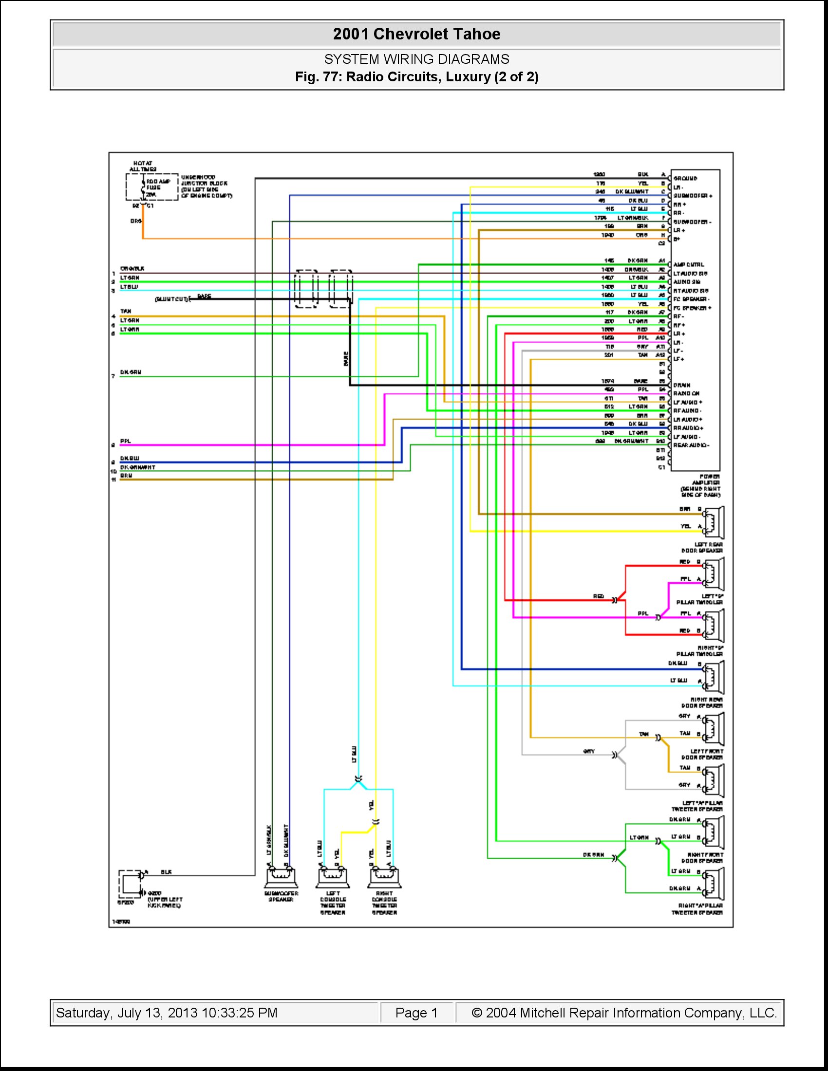
Diagram Delphi Delco Car Stereo Wiring Diagram 05 Tahoe Full Version Hd Quality 05 Tahoe Diagramsite Helene Coiffure Rouen Fr
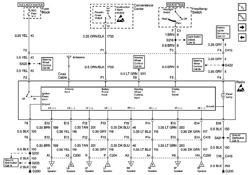
Diagram Delphi Delco Car Stereo Wiring Diagram 05 Tahoe Full Version Hd Quality 05 Tahoe Silverstatewiring Cinemagie Fr

8 Best Engineer Images Fire Sprinkler Fire Sprinkler System Fire Alarm System

Diagram Car Amplifier Wiring Diagram Installation Wiring Diagram Full Version Hd Quality Wiring Diagram Innovativewiringservices 8ktv Fr

Diagram 00 Lincoln Ls Radio Wiring Diagram Full Version Hd Quality Wiring Diagram Diagramdocs Muroduro It
Widar Fire Protection
Professional Chinese Manufacturer Fire Live Alarm Extinguishing Control Panel Buy Fire Alarm System Addressable Fire Alarm Addressable Fire Alarm Control Panel Product On Alibaba Com

Installation Facile Et Commode Du Cylindre Fm0 De Gaz De Systeme D Extinction Rouge

Diagram 96 Chevy Radio Wiring Diagram Full Version Hd Quality Wiring Diagram Seemdiagram Eracleaturismo It
Parts Management Control Plan Engine Diagram And Wiring Diagram

Fm 0 Clean Agent Fire Extinguishing System Tradekorea
Fm 0 Schematic
Clean Agent Suppression Systems Using Novec 1230 Fluid

Diagram 1995 Dodge Radio Wiring Diagram Full Version Hd Quality Wiring Diagram Sunstatewiring Unpugnounmorto It
2
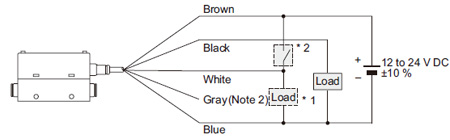
Integrated Display Type Digital Flow Sensor Fm 0 I O Circuit And Wiring Diagrams Automation Controls Industrial Devices Panasonic

Yamaha Ag 0 Wiring Diagram Wiring Diagram Schemas
Www Fike Com Wp Content Uploads 18 01 06 297 Rev 5 Pdf

Bmw 528e E28 Wiring Diagrams Car Electrical Wiring Diagram

Diagram Sanji Car Alarm Wiring Diagram Full Version Hd Quality Wiring Diagram Onelinediagram Rossogranata It
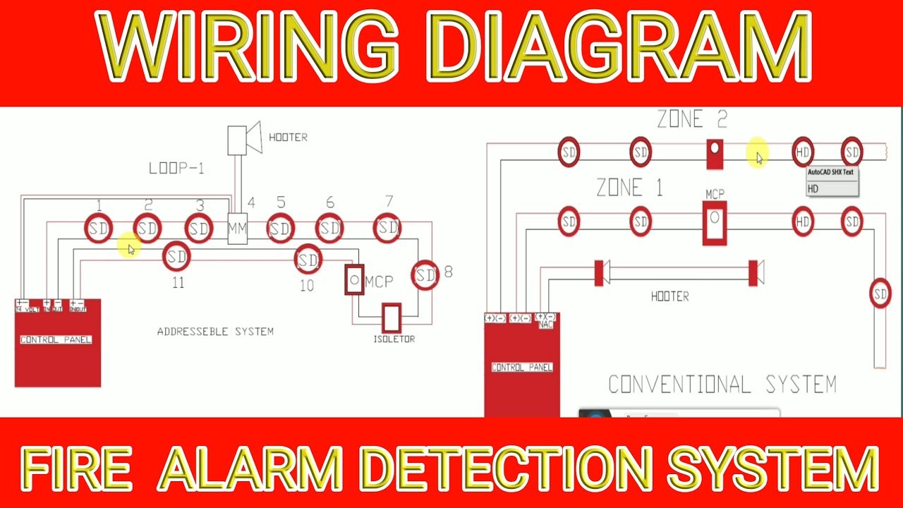
Diagram Class A Fire Alarm Wiring Diagram Full Version Hd Quality Wiring Diagram 12vwiringdiagram Triestelive It

Fm 0 Electrical Fire Detector
2
Diagram Hot Water Heater Wiring Diagrams Full Version Hd Quality Wiring Diagrams Trailerwiringdiagram Lavitadidante It
Www Amerexfire Eu Media 4065 Clean Agent System Pdf
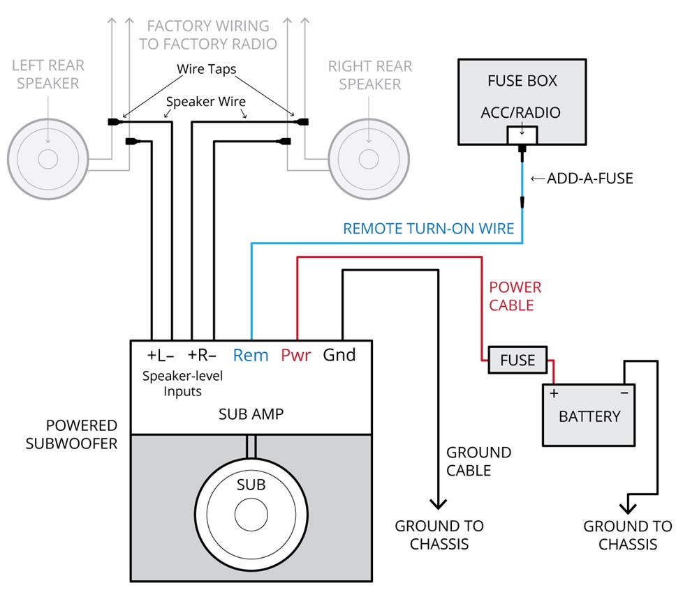
Amplifier Wiring Diagrams How To Add An Amplifier To Your Car Audio System

Imperial Fm 0 Fire Suppression System Simulation Youtube
Amplifier Wiring Diagrams How To Add An Amplifier To Your Car Audio System

Manuals Kentec Electronics Ltd
Kidde Fire Systems Marine Instruments Fm 0 User Guide Manualsonline Com
Diagram Sony Schematic Diagram Full Version Hd Quality Schematic Diagram Imeiphoneunlock Terrassement De Vita Fr

Method Statement For Installation Of Clean Agent Fire Suppression System Method Statement Hq Fire Suppression Fire Suppression System Installation
Q Tbn 3aand9gcq64czh8rn91mvkuonrpo X0xb4fiezqalnvbfoghznvkibsjnh Usqp Cau

Chetan Corporation
Q Tbn 3aand9gcstl5cabwkdoku4oxbzx7qowym Dx5yeonj7rhtcqw Usqp Cau
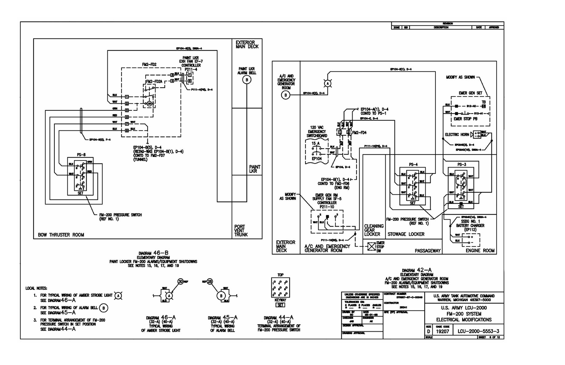
Fm 0 System Electrical Modifications Tm 55 1905 243 24 P0501

Diagram 19 Ford Ranger Radio Wiring Diagram Full Version Hd Quality Wiring Diagram Cyclotrondiagrams Jazzsurlesquais Fr

Diagram 04 Gmc Sierra Radio Wiring Diagram Full Version Hd Quality Wiring Diagram Doordiagram Sergesimon Fr

Gate Opener Gate Opener Wiring Diagram

Construction Standard Specification Section Fm 0 Clean Agent Extinguishing System Pdf Free Download
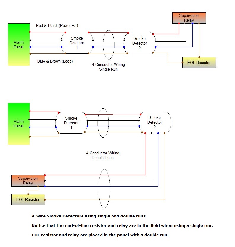
Diagram Home Smoke Detectors Wiring Diagram Full Version Hd Quality Wiring Diagram Lonndiagram Gruppe Freiburg 1 De
Acura Tsx Ewd Fuses Relay Car Electrical Wiring Diagram

Ep3 Automatic Extinguisher Panel C Tec

Widar Fire Protection
Q Tbn 3aand9gcsrph0ynduvgrqvsb1oudfb5pmnsef6gx9s2n0nzh8cbkwt Zsj Usqp Cau

Instalasi Refill Pemadam Api Fm0 Fire Suppression System Presentasi Harga Pemadamapi Biz
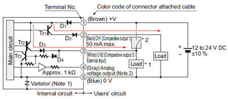
Integrated Display Type Digital Flow Sensor Fm 0 I O Circuit And Wiring Diagrams Automation Controls Industrial Devices Panasonic

Wiring Diagrams Bay City Metering Nyc

How To Install Fm 0 Fire Suppression System Youtube
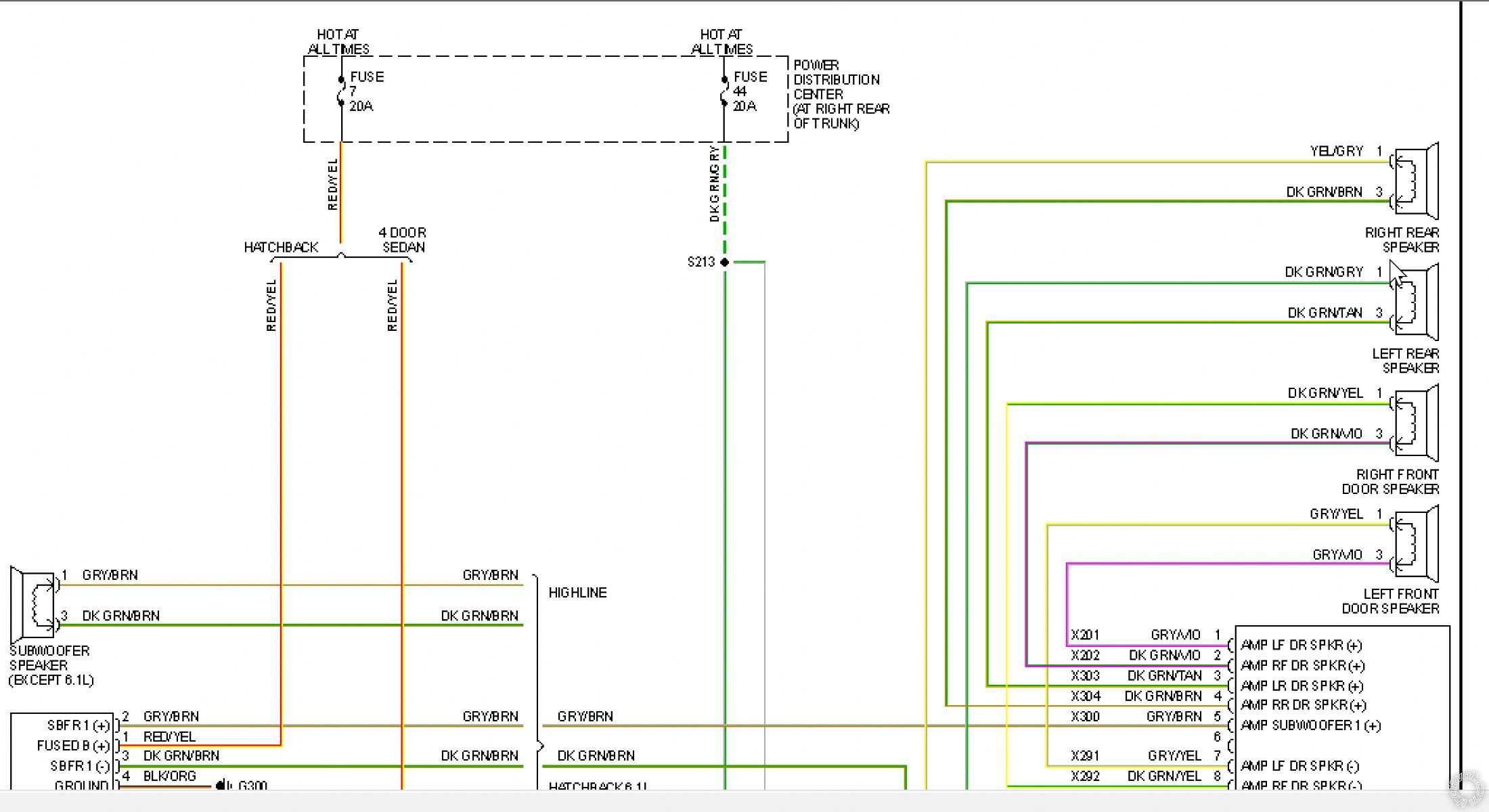
Diagram 1995 Dodge Radio Wiring Diagram Full Version Hd Quality Wiring Diagram Sunstatewiring Unpugnounmorto It
Tbolt Usa Tech Database Tbolt Usa Llc

Fire Suppression Systems Fm 0 Fire Suppression Systems Fire Buckets Mumbai India

Instalasi Refill Pemadam Api Fm0 Fire Suppression System Presentasi Harga Pemadamapi Biz
Widar Fire Protection

Welcome Fire Alarm System Fire Alarm Fire Systems

Diagram Rover 0 Alarm Wiring Diagram Full Version Hd Quality Wiring Diagram Mgbwiringdiagram Liceoartisticomatera It

Diagram 05 Jeep Liberty Stereo Wiring Diagram Full Version Hd Quality Wiring Diagram Roguediagram Comunicazionekoine It

Diagram Rover 0 Alarm Wiring Diagram Full Version Hd Quality Wiring Diagram Mgbwiringdiagram Liceoartisticomatera It
Kidde Aegis 2 0 Release Panel Find Best Fire Alarm Panels Controlfiresystems Com

Modular Fire Suppression System Canovate

Cara Kerja Fm0 Fire Suppression Official Web Distributor Fm0 Fire Suppression
Diagram 40 Amp Relay Wiring Diagram Full Version Hd Quality Wiring Diagram Hrdiagramdrawing Icsgagliano It

Fm 0 Clean Agent Fire Suppression System Hfc 227 Fike
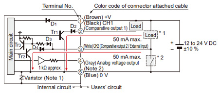
Integrated Display Type Digital Flow Sensor Fm 0 I O Circuit And Wiring Diagrams Automation Controls Industrial Devices Panasonic
2

Diagram Wiring Diagram For A Smoke Detector Alarm Full Version Hd Quality Detector Alarm 12vwiringdiagram Triestelive It

Fire Alarms Jules Bartow Communications Security In The Vein

Diagram 3 Amp Meter Base Wiring Diagram Full Version Hd Quality Wiring Diagram Dwiringdiagram Simoneekevin It
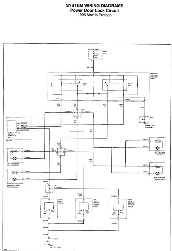
Diagram Mazda 323 Central Locking Wiring Diagram Full Version Hd Quality Wiring Diagram Flashdiagram Helene Coiffure Rouen Fr
Diagram 96 Chevy Radio Wiring Diagram Full Version Hd Quality Wiring Diagram Seemdiagram Eracleaturismo It


